
Showing posts with label failure. Show all posts
Showing posts with label failure. Show all posts
Monday, 11 June 2012
Friday, 8 June 2012

Thursday, 7 June 2012
CAUSES OF FAILURE OF FOUNDATIONS IN BUILDINGS

Causes of Foundation Failure in Buildings
Foundation failure can be attributed to several things. Most commonly foundation failure is caused by the movement of expansive and highly plastic soils beneath different sections of the foundation footings. This movement can be in the form of shrinkage, which causes settlement, or expansion, which causes heave. When dry conditions prevail, soils consistently lose moisture and shrink. When moisture levels are high, soils swell. Regardless of the nature of the movement, it will most likely manifest itself in the form of visible cracks in the foundation walls, exterior brick walls, or interior Sheetrock or plaster walls. Officially, any structure movement is known as differential settlement.
foundation-failure-causes
In addition to expansive soils, subsurface peat, which has a low bearing capacity and deteriorates over time, can also cause differential settlement. Other soil types such as sand and silt also have lower than required bearing capacities.
Poor drainage from yard run-off and gutter downspouts discharging at the base of the foundation are among other causes. Excess moisture around the foundation can cause the soils to become over-saturated and lose “bearing pressure,” or the strength to support weight. When this happens, structures “settle” or sink into the ground.
If soil and water control problems weren’t bad enough, there is also the issue of transpiration. Transpiration is a fancy word for the process of trees and large plantings absorbing the water from the soils beneath and around your home. During an active season, roots extending beneath and around the footings of the house can remove moisture from the soil, causing it to become desiccated. Again, where expansive soils exist this removal of moisture will cause soil shrinkage and settlement.
Plumbing leaks are another major contributor to foundation settlement. Inundating the foundation with water from your home’s pipes will cause foundation failure, as would poor drainage on the outside.
Poor construction sometimes causes settlement in homes, but only rarely.
Failure Analysis Of Mishap At DMRC On 12 July
It was 12th July 2009 which proved to be the darkest day in the history of DMRC. After achieving a milestone of providing a reliable and easy mean of transportation to the capital of India, it is now facing huge problems which are not only causing loss of human lives but also causing immense damage to the most reputed infrastructure organization of India. So far, this company has achieved every target ahead of schedule under the excellent guidance of Mr. Sreedharan.
Let us try understanding what went wrong on that disastrous day
On 12th July, 2009, while lifting segments of the superstructure, an accident happened in the Badarpur – Secretariat section near P-67. The pier cap of pier P-67 got collapsed causing subsequent collapse of the
(i) Launching Girder
(ii) Span between P-66 and P-67 which had got erected and pre-stressed, already
(iii) Segments of the superstructure for the span between P-67 and P-68.
(i) Launching Girder
(ii) Span between P-66 and P-67 which had got erected and pre-stressed, already
(iii) Segments of the superstructure for the span between P-67 and P-68.
The incident left 6 people dead and many injured.
Site Investigation
After visiting the site, following observations were noticed
1. The pier cap of affected pier (P-67) has sheared from the connection point of the pier and pier
cap. It is a cantilever pier cap. It was informed by the contractor and DMRC representatives that the support system for viaductwas initially designed as portal pier till the casting of the pier was over. The shop owners put up resistance against casting of the other leg of the portal and it was subsequently decided by DMRC that this would be changed to a cantilever pier, similar to P-68 which is still standing at site.

2. It was noticed that the prop support of the cantilever has failed from its connection to the pier.
3. The top reinforcement of the cantilever beam does not have any development length into pier
concrete. As learned from the sources, the top reinforcement of the cantilever beam had an “L”
bend of 500 mm only.
concrete. As learned from the sources, the top reinforcement of the cantilever beam had an “L”
bend of 500 mm only.

There is very nominal (or no trace) of shear reinforcement at the juncture.
4. The launching girder has fallen below with the failure of pier cap. Also, the span between P-67
and P-68 has fallen inclined, supported by the ground at one end and pier cap (P-68) on the
other.
and P-68 has fallen inclined, supported by the ground at one end and pier cap (P-68) on the
other.

5. The boom of the crane, used for lifting the launching girder on 13 July, 2009, has failed in bending
and shows clear sign of overloading.
and shows clear sign of overloading.

Analysis
i. The pier (P-67) was initially designed as a leg of a portal frame and subsequently changed to support cantilever pier cap.
i. The pier (P-67) was initially designed as a leg of a portal frame and subsequently changed to support cantilever pier cap.
ii. The same method was followed for P-68 and P-66.
iii. The alignment of track here is in curvature and gradually leaves the median of the road to align on one side of the road.
iv. The longitudinal reinforcement of the pier was protruding by around 1500 mm beyond top of pier.
v. The top reinforcement of pier cap was 36 mm in diameter and had a development length of 500 mm. only as an “L” from the top. There was insufficient bond length for the structure to behave like a cantilever beam.
vi. During launching operation of the launching girder itself, this pier cap developed crack and work was stopped for couple of months. During this period, the cantilever pier cap was grouted in crack areas and further strengthened by introducing prop or jacketing.
vii. However, the behavior of the structure changed due to introduction of this jacket and the cantilever pier cap remained no more cantilever.
viii. The segments of superstructure for the span between P-66 and P-67 was erected and launched and the prop beam / jacketing could sustain the load to that extend.
ix. During the launching of superstructure segments between P-67 and P-68, only 6 segments could be lifted and the whole system collapsed when seventh segment was hooked for lifting.
The sequence of failure is as follows:
a. The support of the prop / jacket got sheared from its connection due to inadequate section / welding.
a. The support of the prop / jacket got sheared from its connection due to inadequate section / welding.
b. The cantilever pier cap which was behaving as a simply supported beam due to introduction of prop / jacket started behaving like a cantilever beam suddenly after failure of the prop which it can not sustain ( It was inadequately designed). So, the so called “cantilever pier cap” collapsed.
c. The launching girder / span between P-67 & P-66 / the temporarily erected segments between P-67 and P-68, all got collapsed in one go.
Crane Failure
The launching girder was lifted by the cranes. However, it needed to be pushed little forward for
unloading it on the ground. So, all the cranes were asked to stretch there booms by some length.
During this operation, the 250 MT capacity crane on extreme left exceeded it’s capacity and the
boom failed and broke down. Since, there were unequal loading on the 250 MT crane by it’s side,
that also failed and broke down. The crane of 350 MT capacity didn’t broke but it toppled with it’s
base. The 400 MT crane remained intact.
Final overview
a. It is concluded that the failure of pier cap occurred due to inadequate prop / jacket. This was coupled with failure of cantilever pier cap due to inadequate development length of top reinforcement of the cantilever pier cap.
a. It is concluded that the failure of pier cap occurred due to inadequate prop / jacket. This was coupled with failure of cantilever pier cap due to inadequate development length of top reinforcement of the cantilever pier cap.
b. The failure of the crane was a case of operational inexperience for such synchronized crane operation. The crane -1 did not have the requisite capacity for the extended boom length and radius. Once crane – 1 failed, the crane – 2 was loaded almost half of the launching girder amounting to around 200 MT. For the extension of boom and radius, it did not have the requisite capacity so it failed, too. The crane -3 was loaded more than it’s capacity. However, in this case the crane got toppled instead of boom getting sheared. The crane -4 did not undergo the severe loading due to failure of other 3 cranes and most of the loads got grounded by that time.
What it taught us?
a. Structural designs should be proof checked by experienced structural engineer.
a. Structural designs should be proof checked by experienced structural engineer.
b. Once failure observed, structure should be as far as practicable abandoned and new structure should be built up
c. More emphasis should be given on detailing of reinforcement to cater for connections and behavior of the structural components.
d. Any make-shift arrangement to save a failed structure should be avoided.
e. Reinforcement detailing in corbels, deep beams, cantilever structures should be checked as per the provisions of more than one type of Standards (both IS & BS should be followed).
f. Adequately experienced Engineer / Forman should be deployed for erection works.
Complete Report on Failure Analysis of World Trade Center
Abstract
This research involves a failure analysis of the internal structural collapse that occurred in World Trade Center 5 due to fire exposure alone on September 11, 2001. It is hypothesized that the steel column-tree assembly failed during the heating phase of the fire. Abaqus/Standard was used to predict the structural performance of the assembly when exposed to the fire. Results from a finite element, thermal-stress model confirms this hypothesis, for it is concluded that the catastrophic, progressive structural collapse occurred approximately 2 hours into the fire exposure.
This research involves a failure analysis of the internal structural collapse that occurred in World Trade Center 5 due to fire exposure alone on September 11, 2001. It is hypothesized that the steel column-tree assembly failed during the heating phase of the fire. Abaqus/Standard was used to predict the structural performance of the assembly when exposed to the fire. Results from a finite element, thermal-stress model confirms this hypothesis, for it is concluded that the catastrophic, progressive structural collapse occurred approximately 2 hours into the fire exposure.
Keywords:
Collapse, Coupled Analysis, Failure, Fire, Heat Transfer, Interface Friction, Structural, Thermal-Stress, World Trade Center (WTC)
Collapse, Coupled Analysis, Failure, Fire, Heat Transfer, Interface Friction, Structural, Thermal-Stress, World Trade Center (WTC)
1. Background
World Trade Center 5 (WTC 5) was a nine-story building in the World Trade Center complex in New York City, NY (Figure 1). On September 11, 2001, flaming debris from the World Trade Center Tower collapses ignited fires in WTC 5. These fires burned unchecked, ultimately causing a localized interior collapse from the 8th floor to the 4th floor in the eastern section of the building (Figure 2). Debris impact was not a direct factor in this failure; the collapse was caused by fire alone.
The structural design of WTC 5 employed a common framing configuration, with steel column-tree assemblies that had beam stubs welded to the columns and cantilevering to support simple-span girders. The connections between the girders and the beam stubs were shear plates attached to the webs with bolts. The floor framing was topped with a concrete slab with welded wire fabric reinforcement.
Forensic evidence suggests that the collapse occurred during the heating phase of the fire. The columns remained straight and freestanding after the collapse (Figure 2), suggesting that the girders never developed catenary action that would have pulled columns inward, particularly as the girders cooled late in the fire. In general, the timing of this failure (early in the fire when occupants and firefighters could be in the building and therefore at great risk) is not typical for steel structures.


2. Finite Element Analysis Approach
For this research, the nonlinear heat transfer and stress analysis capabilities of Abaqus/Standard allowed study of the mechanisms that caused WTC 5 to suffer an internal collapse. The structural plans and details of WTC 5 provided the data for an accurate model of the structural configuration.
For this research, the nonlinear heat transfer and stress analysis capabilities of Abaqus/Standard allowed study of the mechanisms that caused WTC 5 to suffer an internal collapse. The structural plans and details of WTC 5 provided the data for an accurate model of the structural configuration.
The process involved sequentially coupled thermal-stress analyses with a heat transfer simulation to determine temperature history, followed by a stress analysis that incorporated the temperature history as part of the loading. The analyses modeled four structural bays on the 8th floor of WTC 5 (a typical bay is shown in Figure 3) using the mesh detail shown in Figure 4 for both models.


2.1 Heat Transfer Analysis
The model included common spray-applied mineral fiber fireproofing insulation as shown in Figure 4, in which the thermal contact between the insulation and steel, as well as the temperature-dependent properties of A36 steel, were derived from literature.
The model included common spray-applied mineral fiber fireproofing insulation as shown in Figure 4, in which the thermal contact between the insulation and steel, as well as the temperature-dependent properties of A36 steel, were derived from literature.
The 2005 National Institute of Standards and Technology (NIST) report on the performance of the World Trade Center Towers (WTC 1 and WTC 2) provided the basis for the effective heat of combustion and the peak heat release rate of the fire that occurred within WTC 5. The time function of the heat release rate became the input for a Consolidated Fire and Smoke Transport Model (CFAST, developed by NIST) analysis to estimate the upper gas layer temperature history of the fire.
A convective film condition on the faces of the assembly exposed to the fire environment modeled the thermal loading, using a heat transfer coefficient characteristic of turbulent, natural convective heating. Subsequently, the results of the CFAST simulation prescribed the sink temperature history of the model.
2.2 Stress Analysis
The three-dimensional temperature distribution history of the steel assembly based on the heat transfer analysis became part of the loading in the stress analysis. Other loads applied to the model included gravity to model the weight and 39 kips of pretension in each bolt to produce an idealization of the static and kinetic friction conditions at the connection.
The three-dimensional temperature distribution history of the steel assembly based on the heat transfer analysis became part of the loading in the stress analysis. Other loads applied to the model included gravity to model the weight and 39 kips of pretension in each bolt to produce an idealization of the static and kinetic friction conditions at the connection.
The model utilized nonlinear, temperature-dependent stiffness and thermal expansion properties of A36 steel based on experimental data (Harmathy, 1993). Therefore, the temperature distribution history dictated the steel strength and stiffness properties. The nonlinear material properties, together with modeling to account for geometric nonlinearities, produced high-fidelity analyses of structural performance during the fire.
2.3 Failure Criterion Analysis
Forensic evidence suggests that the shear connection failures in WTC 5 were due to rupture of the web portion of the beam stems. This type of failure occurs when the bolts bear against the weak side (i.e., acting toward the free end of the member) of the bolt holes. Bearing stress of this type causes shear planes to form in the web steel. Finally, cracks along the shear planes cause catastrophic failure of the shear connection.
Forensic evidence suggests that the shear connection failures in WTC 5 were due to rupture of the web portion of the beam stems. This type of failure occurs when the bolts bear against the weak side (i.e., acting toward the free end of the member) of the bolt holes. Bearing stress of this type causes shear planes to form in the web steel. Finally, cracks along the shear planes cause catastrophic failure of the shear connection.
A simple model consisting of a single bolt and holes in connected plates provided data on the material strain condition at the point of catastrophic rupture. A failure load, derived using the AISC Steel Manual of Steel Construction (2001), applied to the single bolt model produced the required strain data. The plastic shear strain for the failure load produced the failure criterion for the full connection models.
3. Simulation Results
The temperature distribution near a shear connection after two hours of fire exposure is shown in Figure 5. In general, the average temperature of the steel agrees well with estimates from hand calculations. The results of the thermal model show that the insulation delayed the transmission of heat to the steel during the fire exposure as anticipated. Moreover, the results show that the upper region of the steel assembly remained cooler due to the heat sink effect of the overhead concrete slab.
The temperature distribution near a shear connection after two hours of fire exposure is shown in Figure 5. In general, the average temperature of the steel agrees well with estimates from hand calculations. The results of the thermal model show that the insulation delayed the transmission of heat to the steel during the fire exposure as anticipated. Moreover, the results show that the upper region of the steel assembly remained cooler due to the heat sink effect of the overhead concrete slab.
The temperature of the beam stems at the shear connection was approximately 400 °C hotter than at the column after two hours of fire exposure. The beam stem was exposed uniformly to the hot gases and began to heat in accordance with its heat transfer properties. The cooler column (and adjacent structure) acted as a heat sink that tended to moderate the temperature rise of the beam stem immediately adjacent to the column. The shear connection was located far enough from this critical heat sink that it remained relatively unaffected, and quickly rose in temperature along with the simple-span girder.
As the steel in the compartment heated in the first hour of fire exposure, it expanded, causing the floor girder to elongate significantly and close the gap between it and the beam stem. This elongation caused relatively harmless compressive stress concentrations as the bolts pushed into the beam stem web.
As the temperature of the steel assembly increased further, the frame rigidity decreased steadily,causing the floor girders to deflect significantly. This deflection caused the lower flange of the girder to contact and deform the beam stem web, forming a fulcrum at the contact point. After about two hours of fire exposure, the loss of rigidity in the steel “outpaced” its thermal expansion, and the top bolt of the shear connection, which was pushing into the web, started to pull toward the end of the beam stem web (Figure 6).


4. Discussion of Results
According to the failure criterion derived and the results of the thermal-stress analysis, the heat-weakened shear connection experienced complete failure after approximately two hours of fire exposure. The deformation and failure of the shear connection predicted by the Abaqus model are very similar to those exhibited in failed connections in WTC 5. The angles at which the bolts pried against the bolt holes are similar in the model and the specimen (Figure 7). Moreover, photographs of failed beam stems show web deformations indicative of the fulcrum action.
According to the failure criterion derived and the results of the thermal-stress analysis, the heat-weakened shear connection experienced complete failure after approximately two hours of fire exposure. The deformation and failure of the shear connection predicted by the Abaqus model are very similar to those exhibited in failed connections in WTC 5. The angles at which the bolts pried against the bolt holes are similar in the model and the specimen (Figure 7). Moreover, photographs of failed beam stems show web deformations indicative of the fulcrum action.

5. Conclusion
The sequentially-coupled, nonlinear thermal-stress modeling capabilities in Abaqus/Standard allowed study of the structural behaviors that led to the internal collapse of WTC 5. The analysis show that this collapse occurred approximately two hours into the heating phase of the fire after the simple span girders deflected enough to tear the connecting bolts out of the webs. It is not the precise time of failure which is aramount, but the fact that the structure failed uncharacteristically during the fire’s heating phase, rather than during the cooling phase when most fire-induced collapses occur.
The sequentially-coupled, nonlinear thermal-stress modeling capabilities in Abaqus/Standard allowed study of the structural behaviors that led to the internal collapse of WTC 5. The analysis show that this collapse occurred approximately two hours into the heating phase of the fire after the simple span girders deflected enough to tear the connecting bolts out of the webs. It is not the precise time of failure which is aramount, but the fact that the structure failed uncharacteristically during the fire’s heating phase, rather than during the cooling phase when most fire-induced collapses occur.
The fire that caused structural collapse in WTC 5 was a severe, complete burn-out fire. As such, it is not unreasonable that the structure would experience substantial damage. However, the failure of the building to achieve the preferred performance, with the framing system surviving at least into the cooling phase of the fire, follows from the absence of analyses and design for fire exposure.
The present approach to fire protection engineering in much of the United States is primarily prescriptive, often employing propriety products to insulate structural elements and active fire suppression systems to control fire growth. Such approaches would not lead to an appreciation for vulnerabilities such as apparently existed in some of the detailing in WTC 5.
Analytical, performance-based approaches, more akin to common design for wind, seismic, and other environmental loads, are more likely to reveal critical aspects of building performance in fires, and provide engineers with the understanding they need to create designs that are robust, raise safety for occupants and firefighters, and are cost efficient.
Accurate, detailed finite element modeling can be used to assess the fire endurance of steel structures. Such simulations can be used to develop pre-engineered solutions to building codes. Additionally, knowledge of the fire endurance behavior of WTC 5 can further the understanding of firefighting risk in existing buildings of similar design.
In the case of WTC 5, relatively simple detailing changes would have enhanced the structure’s fire resistance. Slotted holes in the girder webs or increased spacing between the end of the girder stubs and the beginning of the simply supported center spans would have allowed more girder rotation without developing the prying action that tore out the girder webs. Keeping the shear connection near the face of the column would have reduced the temperature of this critical connection, thereby maintaining higher temperature-induced tear-out strengths during the fire.
In the more general case, we must acknowledge that many buildings in current use have unappreciated vulnerabilities. While analyzing and retrofitting for these vulnerabilities in existing buildings could be undertaken if justified for certain framing systems (e.g., perhaps for column-tree assemblies, if risk analyses and system testing verified heightened risk for the building system generally), finding the critical shortcomings in the present building stock would be a prohibitive exercise. However, modest expenditures of engineering effort during the design phase for new buildings can reveal fire performance weaknesses that can be avoided, often at minimal cost to construction.
6. References
1. Manual of Steel Construction: Load and Resistance Factor Design, 3rd ed., American Institute of Steel Construction (AISC), 2001
2. Harmathy, T.Z., “Fire Safety Design and Concrete,” Longman Scientific and Technical, United Kingdom, 1993
3. World Trade Center Building Performance Study: Data Collection, Preliminary Observations, and Recommendations, Federal Emergency Management Agency (FEMA), New York, 2002
Tacoma Narrows Bridge Collapse
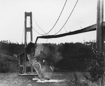
It was an unfortunate morning of 7th November 1940 when winds having speed of 42 miles per hour suddenly twisted the Tacoma Narrows Bridge and lead to its collapse. This accident though didn’t look any lives but it surely made the civil engineers to think new ways to combat bridge collapses.
Some of the important statistics of this bridge are -
It is located in Tacoma, Washington, USA and was completed in 1940. This was a suspension type of bridge with length of 7,392 feet and was built at the cost of $6.4million.It had the longest span of 2800 feet.
It is located in Tacoma, Washington, USA and was completed in 1940. This was a suspension type of bridge with length of 7,392 feet and was built at the cost of $6.4million.It had the longest span of 2800 feet.
The bridge was designed by engineer Moisseiff who had strengthened it with a solid steel girder beneath the roadway.But the problems started soon it was opened to traffic.Under strong winds, it swayed much beyond the permissible limits and thus sent rippling waves along the deck. It took just 4 months before this bridge collapsed after its completion.
On investigating it was found that the solid steel girders provided to strengthen the bridge were actually blocking the wind which caused the bridge to twist.Due to this a swirling motion developed which ultimately lead to the collapse. After knowing the reason for collapse a new bridge was constructed which had a truss so that it can allow the passage of wind
This bridge also got the name “Galloping Gertie” due to its unusual twisting and rolling behavior.
See this video to see how this “Galloping Gertie” used to sway.
Subscribe to:
Posts (Atom)